It also introduces techniques for visitors who want to learn more. Limit Dimensions - In limit dimensioning only the maximum and minimum dimensions are specified.

Electrical Symbols Electrical Circuit Diagram Electrical Schematic Symbols
The GDT language consists of a well-defined set of symbols rules definitions and conventions.
. State in order ie. Basic types of symbols used in engineering drawings are countersink counterbore spotface depth radius and diameter. Most of the symbols used between ASME and ISO are identical.
Circularity The circularity also called roundness. It uses a symbolic language on engineering drawings and computer-generated three-dimensional solid models that explicitly describe nominal geometry and its allowable variation. GDT symbols are known universally as a method of specifying requirements without using notes or words on the drawing.
To indicate that a profile of a surface tolerance is not symmetrical about the true profile this symbol is used. C The following symbols are used to represent specific dimension types in GDT standards. Geometric Dimensioning and Tolerancing GDT is a system for defining and communicating engineering tolerances and relationships.
Total Runout is how much one entire feature or surface varies with respect to a datum when the part is rotated 360 around the datum axis. 3 Marks ii For two of the three GDT dimension types shown describe in detail with the aid of a diagrams how these dimensions can be applied for. Symbols can specify things such as repetitive features diameters radius spotfaces and counterbores.
GDT is an acronym that stands for Geometric Dimensioning and Tolerancing. GDT is an acronym that stands for Geometric Dimensioning and Tolerancing. The symbols are created to look like the requirement they identify.
It is a system of symbols rules and definitions used to define the geometry of mechanical parts. In geometric dimensioning and tolerancing GDT a unique set of GDT symbols are used to define the relationships between part features and measurement references. Yes MMC or LMC applicable.
Unilateral and Unequally Disposed Profile Tolerance. When used with dimension lines the high limit is placed over the low limit. It is a symbolic language used by designers to communicate manufacturing constraints and tolerances clearly.
GDT stands for geometric dimensioning and tolerancing. It is an efficient way of communicating measurement conditions and specification of a part. GDT defines degree of accuracy and precision required on controlled feature of part.
It is a precise mathematical language that can be used to describe the size form orientation and location of part features. The value following the symbol is the amount of the tolerance that is in the direction. Total runout controls both the amount of variation in the surface as the part is rotated but the amount of variation in the axial.
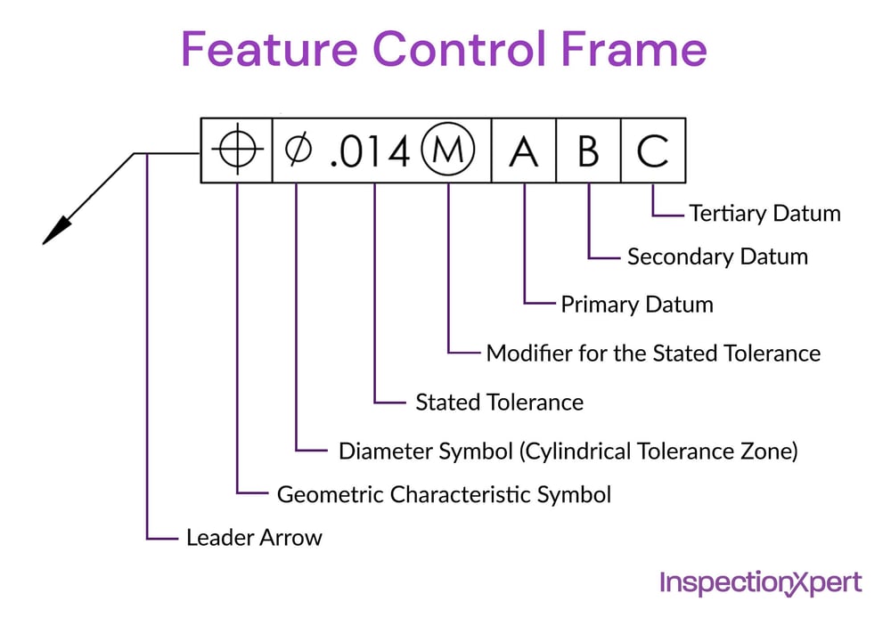
Geometric Dimensioning Tolerancing GDT is a language representative of engineering drawings to classify deviations and tolerance of part measurements and geometric analysis. Diagram of a GDT annotation using the ASME Y145 standard. One of the benefits of GDT is the usage of common symbols that are used to further tolerance a part all of the different characteristics of a component that can be critical.
Below is a table showing the 14 standard geometric tolerance symbols used in geometric tolerancing as defined by ASME Y145. Designers and engineers utilize this international language on their drawings to accurately describe part features on the basis of size form orientation and location. This page shows a list of GDT symbols and associated symbols used by ISO and ASME.
GDT is very important part of mechanical product design. This information is conveyed in the form of annotations included in. Geometric Dimensioning Tolerancing GDT is an international language that is used on engineering drawings to accurately describe a part.
Consisting of symbols this language is used to define the allowable. Learning GDT From Scratch provided by KEYENCE walks you through the basics of geometric dimensioning and tolerancing datums and measurements by coordinate measuring machines. The GDT symbol for LMC is a circled L.
The true position theory and the specification of tolerance zones are also explained. The first value in the feature control frame is the total width of the profile tolerance. All of this is possible when the concurrent engineering team is involved with.
See also MMC and RFS A given geometric tolerance may be defined in relation to a certain FoS datum being at LMC or at MMC. As in major diameter or major characteristic for sampling level MAX. The symbolic language in GDT describes the geometry and allowable variation or error it can specify the requirements of accuracy and precision of the CNC machining parts.
GDT is used to define the nominal theoretically perfect geometry of parts and assemblies to define the allowable. This page explains the 16 symbols used in GDT and the classification thereof. Learning GDT From Scratch provided by KEYENCE walks you through the basics of geometric dimensioning and tolerancing datums and measurements by coordinate measuring machines.
This symbol is used to describe the required roundness of an object. It tells the manufacturing staff and machines what. GDT Flatness is a common symbol that references how flat a surface is regardless of any other datums or features.
Geometric Dimension Tolerance GDT is a system for defining engineering tolerances. For shafts external feature of size LMVS LMS - Geometrical Tolerance For hole internal feature of size LMVS LMS Geometrical Tolerance. 1 2 3 the specific GDT dimension type that each of these symbols represent.
This information is conveyed in the form of annotations included in the design of the part. GDT Geometric dimensioning and tolerancing is a system used to define and communicate the tolerances for engineering designs and computer-generated 3D solid models. Here are more commonly used engineering drawing symbols and design elements as below.
GDT is one of the most powerful tools available that can improve quality reduce cost and shorten delivery time. It is a symbolic language used by designers to communicate manufacturing constraints and tolerances clearly. GDT Symbols Reference Guide from Sigmetrix.
Engineering Drawings Gd T For The Quality Engineer
Gd T Geometric Dimensioning And Tolerancing

Mechanical Drawing Symbols From Mechanical Engineering Fluid Power Equipment Mechanical Engineering Design Engineering Design Mechanical Design

0 Comments